Electronic Hardware Design
Show original YouTube description
Show transcript [en]
our next talk is uh someone who's you you might have seen on the regio desk he's also been helping out on staff um we have a strong sort of electronics um uh uh community uh besides canberra uh with our electronic badges that we do every year and josh is a part of that community and quite often does uh um you know beginner uh workshops for people to help them get into electronics um today he's going to talk about um i think i've actually not turned the page sorry yeah so electronic hardware design that was probably one i should have remembered i'm saying please round of applause for josh so yeah g'day everyone um as kylie has
mentioned i do a lot of electronic design and at the last b-sides i was hanging up in the hardware village a lot of people had the badge that echo made it was awesome and had questions how would they design their own and so i thought it might be interesting to give a quick rundown from start to finish on how you'd build a circuit board this won't be enough to teach you how to do it but it'll give you the tools that you can go home and possibly bring something cool to next year's b-sides so with that said there's going to be roughly two parts to the talk uh the first first part is gonna be a little
bit of theory uh which might get a bit boring but the second part is going to be fun uh which is where i'm talking through a number of boards that i've made including that bow tie which if anyone saw me at red joe has been lighting up and i'll turn it on at the end um so potentially the most boring but the most important part is setting up the requirements at the start now for a conference badge like this i argue the most important thing is that it looks good and so in this case i choose to make it look like a bow tie and i also decided to add a bunch of leds to it
now partially due to covert partially because you're not going to be able to touch it i thought i'd also add a microphone so that you can talk to it or light up or change colors and it's a nice way to interact with it if it's not going around your neck all day you might not have to be too concerned about this but in this case they were the primary objectives in designing the board so the first place you might be wondering is well how do you start this you know what you want to make but where do you actually look for it and this is where just jumping on the internet and finding similar projects so in my
case i just searched sound reactive leds also known as a vu meter you might see as like the audio levels and i found a bunch of tutorials on where you go about designing that um in particular adafruit and sparkfun uh are two companies they make a bunch of open source hardware and most importantly do a bunch of really great documentation on how you actually implement them boards and make things work so now that was the first step for this badge but other places you might find is open source hardware so all my works up on github you can see the projects that i've worked on you'll also find hacker day i o has a bunch of other projects out there
otherwise the chip manufacturers really like selling you their parts and so they'll have evaluation boards they'll have application notes and they'll have the data sheet which has all the information you need to get your board into the world once you've figured out the parts that you want to use the next step is called schematic capture which is basically where you draw a big picture that shows how everything's meant to be connected the schematic is quite nice and that you don't have to follow the laws of physics when you're doing this so if you have a look up at the image there on the right you'll see that the pins aren't in the right order and you also see that this isn't the
same form factor as what you actually put on the circuit board and that's good because if you look at it you can see on the left we have the resistors and the capacitors which set our timing circuit on the top we have power on the bottom we have ground and then on the right we have our output um and as you can see there's no wires crossing you can add labels and another thing i've done with this is i've added a comment down below so essentially what's that there is this little magpie which is flashing so it's at roughly one and a half hertz and the only way i know that is because i've drawn it down underneath
on the schematic before you go on to the next step which is layout i thought it might be interesting to see what the insides of the circuit board looks like i'm sure i'm sure we've all seen the green rectangles inside electronic devices but this is what the cross section of them looks like um so starting at the top right we have what's known as a silk screen and this is where you have all the device markings the board name and all the reference designators for all the components underneath that we have all the green which is on the board which is known as the solder mask and what what this does is it stops the
solder flowing all over the board so what you'll have is solder mask top and bottom and then you'll just remove it where you have pads now traditionally it's been green as you can see on our badges here i believe it's black there's a bunch of different colors available which can make your board look pretty cool moving over to the left we have what's known as a plated through hole or a via what these allow you to do is jump from the bottom of the board down to the top of the board down to the bottom and so you can use both sides of it in this case here this cross section is actually a four layer board and so you
can see the v it touches layer one layer two and then i believe layer four down at the bottom moving across the left we have the external copper which on a two layer board is all the copy you'll have you'll have some on the top some of the bottom this is the traces you can see running around and then because this one's here is a full layer board you also have an internal layer and something like your mobile phone might be 10 or 20 layers so there's a lot inside and then finally it's all held together by what's known as fr4 or glass fiber which is just kind of gives it its mechanical properties so now you kind of know what the insides
of the circuit board look like it's time to lay it out and so basically this is the biggest game of connect the dots that i've ever played uh because what happens is on the schematic side you tell basically yourself what you want to look like and then when you go into layout the cad tool helps you join everything the difference is you have to obey the laws of physics this time so as you can see here i've picked an eight pin part with a kind of two rows on each side i've put the capacitors and the resistors that we saw on the previous page there uh and as you can see also in the middle
where it goes to red i've had to use a va to go onto the other side and come back up now when you've done all of that you have the schematic done your layout done and it passes all the design rule checks this is when you can now go out an audio board which is the exciting time so typically what you do from the pcb is export what are known as your gerbers which are manufacturing files give them a quick review to make sure everything looks okay then upload them to a there's a plenty of board houses online the most important part when you're uploading it is picking the color that you want but you can obviously do another bunch
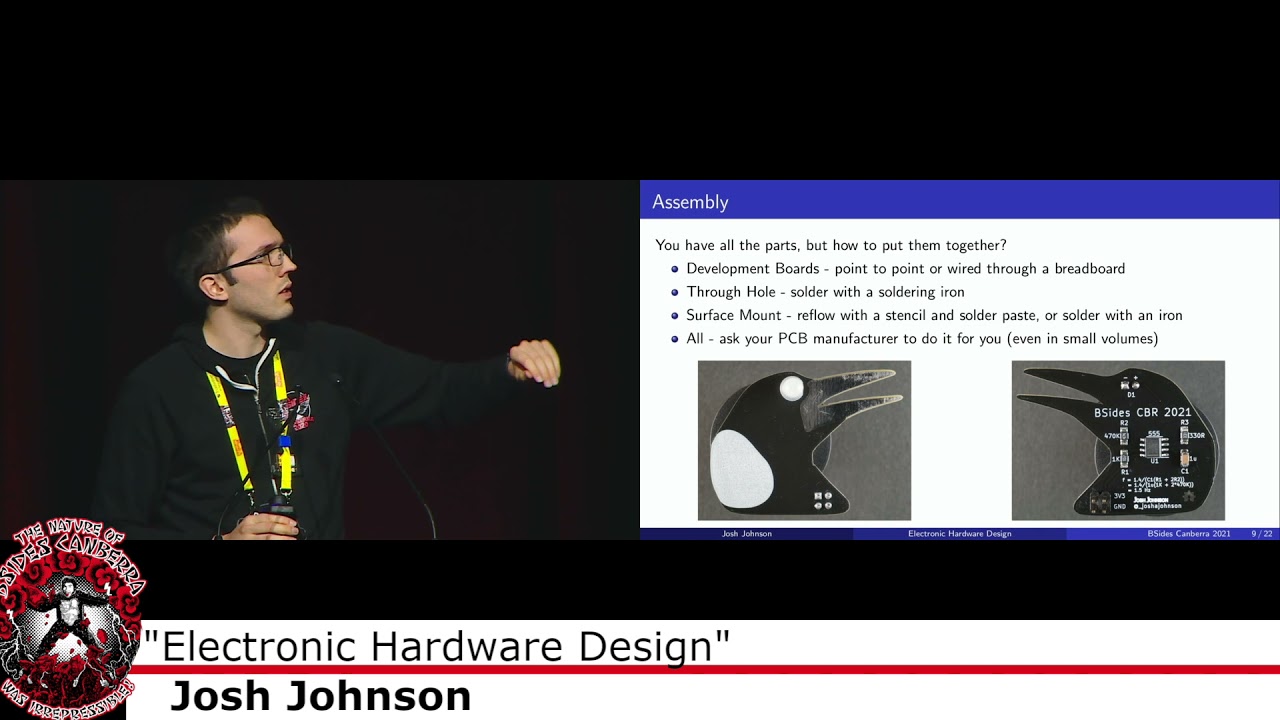
of options there now onto the component side of things from the schematic you can export what's known as a bill of materials which is all the parts so in this case here you had a triple five timer you had a few capacitors a few resistors and the led normally what i would say is after you finish designing a circuit board take a day or two off to relax and then order your parts however there's a massive component shortage right now and so what i normally recommend doing is as soon as you figure out what parts you want buy them because they're probably going to be out of stock by the time that you're done now on to assembly now depending on what
parts you pick so as you can see there on the right uh they're all surface mount parts but they're quite large probably about twice the size to the parts inside your batch if anyone has pulled them apart and so with that you can solder them by hand with a soldering iron um but depending on if you say doing the badge for example you might want to use a solder paste stencil and refloat in the oven uh i'll talk to those methods later but in recent years if you look at those parts you're thinking these are way too small a lot of the circuit board manufacturers will also offer assembly services even in small volumes which makes it a lot
more accessible so with that i'll go on to the boards i've designed as examples so my goal uh for this year was here just have something nice and colorful around my neck i'll see if i can turn that on um but i also wanted to pick parts i'd never worked with before so this was an actual representation of if i was going into this blind and had no idea what i was doing so in this case here i found a instruction from adafruit and so what they had they had their feather development board which is the black one in the middle they also had the leds at the top and the microphone you can see
in the bottom right um i also decided to add an accelerometer accelerometer on there but it didn't end up making onto the final design um now doing on a breadboard like this is great for a first prototype because if you find that something doesn't work such as the accelerometer you can just pull it off and reuse it on another project it's also really good because you might find that certain pins on the micro controller can only do certain things so some of them might not be able to do an analog input other ones might not be able to do a high speed data output and so you can just plug the wires in and out until you get
everything working however there's one massive problem with this is that if i wore that around my neck it'd probably fall apart in the first five minutes and so we need to find something a little bit more permanent for the conference and so this is might be the next step once you've done your breadboard prototype is basically replacing all the wires that are on the breadboard with traces on a circuit board so in this case here we still have the microcontroller in the middle and the microphone down the bottom just like we had on the previous board i have called this a through-hole pcb but there are surface mount leds and capacitors around the outside however they're very large and very easy
to solder but you could potentially do it all through hole if you would like this board is an identical one to one except for the two extra leds it's identical to the breadboard prototype which meant as soon as i uh soldered it together i could copy the exact same phone so firmware over to it and it was off and running now this is great if you're going to do a small number of boards um because there's relatively little engineering time that goes into getting it working uh compared to something i'll show you later and it'd still be quite nice and easy to assemble however if you wanted to build a few thousand of these such as your conference badge
doing this by hand will be a lot of manual labor and it might not scale too well so i'll just quickly run you through how you might go about designing that type of board and so you can see here that's the schematic that's basically all it is there's a bunch of extra leds off onto the other side but you basically have the microphone on the left the micro controller in the middle and then the leds out on the right um a few extra things such as the mounting holes so you can run them i can't pronounce lanyard and then you also have a little um solderable jumper if you want to change the gain but i didn't end up using that um in
this case here there's four unique parts and 26 parts overall and it's fairly straightforward to layout and assemble so speaking of the layout here it's just a two layer circuit board uh we have a ground on the bottom we have all of our power and signal on the top um i was able to pull the footprints for these um from libraries available online so i didn't need to draw them however i did do them myself if i wanted to and that actually caused a problem later um but it's fairly simple they're all uh parts are in the kycad library you just drew a nice big circle around the outside and it's good to go um speaking of
assembly uh it's very straightforward so just a soldering iron to solder all the through-hole parts and the same with all the surface mount parts they're quite big and so they're nice and easy to do by hand um one mistake i did make because i really wanted the cymbals to look nice is that i had the headers for the microphone out 180 degrees but it was fairly easy to fix with some wires uh and speaking of firmware because i was using the same development board with the exact same wiring and schematic as the breadboard it was just as simple as copying it over uh now on to the final design which i've got around manic now and if yeah anyone
saw me at reggio you probably saw it uh doing its thing um this is kind of what i was hoping to get to as the final project um i had you can actually wear it as a bow tie but it's nicer to have around on your lanyard and so in this case here i want it to be looking really good which a green circle for me doesn't look quite as nice as a bow tie i wanted it to also look a bit nicer and that all you have on the front is the leds you can't actually see the brains behind how it works in saying this however there's a lot more time and effort that goes into
bringing this up and as i'll discuss later there are a few mistakes um but the other nice thing about this is is let's say we wanted to make this the conference badge for next year not that i think we should it would be fairly easy to build a bunch of these because with the exception of the microphone it's all surface mount parts and so you can just run it through a machine very easily but it does take a lot more time to set up at the start um so i'm not expecting to be able to read the schematic i'm just trying to show that there's a lot more parts on this so instead of before where we had the
microcontroller dev board from adafruit um what i've had to do is i've had to break all those individual parts that was handled for us on the micro on the dev board out by itself so you can see up in the top left we have usb going down the left we have power and charging then we have the microphone sorry the microcontroller in the middle uh off to the right we have the microphone a few kind of things that just hold everything together in the bottom right and because there are so many leds on here it has a completely separate page which is somewhere in the middle now this obviously takes a lot more time a lot of the parts that i've used on
this schematic here weren't available in the default libraries for the cad tool that i used so i had to design them up myself and all up we had 30 unique parts and 92 parts total so there's a lot more parts to put together so if you just want to build one or two of them it might not make quite as much sense layout for this was a little bit more complicated but not too much it's still a two layer circuit board i have all the leds on the front and everything else on the back it's using some smaller surface mount parts similar to what's in your badge today so they're small enough i can do
them without a microscope which is nice doing the artwork and the outline for this i'm not very good at graphic design but i was able to pull in a photo through inkscape that i was able to define the board outline so that's how we got it to look like a bow tie instead of just using the inbuilt drawing tools i also was able to import some graphics for the front so it kind of looks like a bow tie another thing with this is that i fully 3d modelled it because i was doing all the components kind of from scratch and so what this allows you to do is to see exactly what it's going to look like before you get
it ordered in my case it was used to design the little 3d printed part which will hold it around your lanyard but take for example the badge we've all got around our next right now a lot of effort i imagine would have gone into making sure the injection molded plastic in the middle was going to fit and doing this you can design the mechanical parts see if it's going to work if not you can move the bolts and things around until it does and keep on iterating so you know it's going to fit and everything work properly when you get it back onto assembly of this like i was saying it's a two-sided we have parts on both sides so it means
we're going to need to make it go through the reflow oven twice and so this is a slightly more kind of advanced and complicated method what we do is we get what's a solder paste stencil which is basically a big sheet of stainless steel where we cut our holes out wherever we want solder paste then we squeeze a squeezy squeegee the solder paste over the circuit board and then we have paste on all the pads that we want we then put the parts onto those pads put them in the reflow oven and about seven minutes later they come out all soldered on if you don't have a reflow oven you can also use a hot air
gun which is good if you've got a small number of parts but for a big board like this and i do this a lot so it saves a little bit of time one cool tool that i've found recently with this is known as interactive html bom um it's a it's started as an add-in for kai cad but it's on a lot of the cad tools both open source and proprietary and what it allows you to do is basically you import your bill of materials you give it the board file and then it will tell you where to place all the parts so you can see here i've selected the buttons that are on the back one for reset and two so i can
toggle the state and when i get to that line it will highlight where the buttons are it can show me the orientation and i can put them down and that's particularly helpful for when you've got a bunch of small capacitors and all the footprints look identical but you only need to put them in two or three positions so for those out there that are doing assembling boards at home this might be something interesting to look at getting the firmware up and running on this it was also a little bit more challenging because unlike when we buy the board from adafruit it already has the bootloader and in this case i'm actually running python on the board
just because it's nice and easy to program you plug it directly into your computer shows up as a memory stick you can then edit the code.pi file save it and it runs again however when you get a microcontroller from the vendor there's nothing on there and so you first have to flash a bootloader which is what the four pins over on the right are that requires an external programmer you plug in you put the bootloader on there then once the bootloader is on there you can plug in usb and put circuit python on and then once circuit python's on there you can put your firmware uh and if you're anything like me you put the code on there and nothing works and
so after a little bit of debugging i found a few issues including but i didn't actually hook the microphone up to the microcontroller which for some reason causes uh some problems and there are also some issues with the power circuit but i'll show you how i fix them later on um so all up whereas the earlier boards took somewhere between half an hour and two hours to get the firmware up and running this one took me about four days all up by the time i added some extra features that were on this um but not on the previous development boards um so yeah here are some of the photos of the mistakes that i've made
so you can see this was just simply in the schematic i had the output of the microphone labelled as microphone out i had the input into the micro uh into the microcontroller labeled as mic in or something like that and of course they don't connect because they're different names this is where the electrical rules check which is a tool in the schematic can help you find some mistakes but there are plenty like this that just won't spot but fortunately we're able to fix that and there was also an error on the power circuit side of things a part was in opposite direction to what it normally is i didn't pick it up because i designed these boards
two very late nights back to back but were able to fix that there and then although i've been talking about making blinking things that around your neck that are really cool for a conference that kind of process i've just outlined can be used for absolutely anything so in particular recently i've been interested in fpgas with open source tool chains fpga stands for field programmable gate array they're used when you need to put a lot of data through in parallel so for example the part in the top left-hand photo you can find one of them inside an elgato cam link to do a lot of the hdmi to usb processing and then down in the bottom
left there there's a slightly smaller fpga from the same family that i've used in earlier that earlier version of that board for a lot of education work and i know there's a few people in the building now that actually have one of them probably sitting in a drawer somewhere um outside of that i've also done a bit of work on the rf side of things so there's a low cost vector network analyzer in the top right what it is it's a tool to measure antennas and other rf components they're normally quite expensive but kind of going through the process i went through there but optimizing for cost instead of performance i was able to get one that works pretty
well in a small form factor and small price um and then i had some leftover parts and so in the bottom right hand corner you can see a board that's in the same feather kind of physical format as both the fpga and the microcontroller i used in the prototyping stages and this just plugs in on top and allows you to generate signals for some testing other examples that might be more security related that we've seen over the weekend if you have a look at the bus side from what silvio spoke about this morning um you'll see that's where you've taken a off-the-shelf microcontroller but broken or broken all the pins out to locations where it makes it really easy
to plug in a spy flash chip or round the cables over to your device under test you're trying to probe um and then if you also saw iggy's talk yesterday he was just building something as a one-off to dump the flash of his device but if there were a lot that needed to be made for your team or if it was something that you were doing quite often you might be able to kind of follow the same steps to come with a tool that kind of similar to this it's not going to fall apart and you can use it for days or years at a time and so with that said that's coming to the end um if you are interested in
learning more this talk's just trying to be an introduction to make you aware of the process and things you might be interested in looking at if you jump onto that github link there all the slides along with the design files are available obviously can't recommend ordering either of the two boards that i've just spoken about because they're not going to work but you can have a look at how i've done the schematic how i filled out the bill of materials i have all the assembly documents and everything there as well there's also a whole heap of links to much more in-depth uh kai-cad which is my tool of choice it's an open source ada tool
there's also a bunch of other options out there but there's a bunch of links to doing more in-depth design that will give you kind of a more detailed view and then finally if you have any questions please don't hesitate to say hello i should hopefully be pretty easy to spot with this i'll be hanging around the t-shirt area of the salvo otherwise you can find me online at those places whether you just have a question you're interested a project that i've worked on or what i'd love to hear is that if you're about to order your own board and you have any problems doing that or you just like a second set of eyes so maybe you don't have many uh as many
flying wires as i do please don't hesitate to get in touch so with that um thanks for listening and i'll pass it back to kylie thanks joshua's uh really interesting we have a few questions on the slack um which supplier either australian or or overseas would you recommend for small run boards uh so i'm not going to name any specific names but there are a bunch of lower cost chinese board and assembly houses that i've used depending on the quality and the quantity that you need there are various pros and cons unfortunately for this kind of hobbyist level stuff there's not really a cost-effective solution in australia but there are a number of very high-end
board and assembly houses here that do amazing work this one i'm not sure if you answered it later in the talk but for hobbyist grade smd board manufacturer and prototyping tools do you recommend anything in particular or is the standard still a cheap taster oven modified for solder reflow yes so i basically use all the cheap tools off ebay um you can get a hot air gun for about forty dollars i can't remember the product code if you come have a chat to me we can find it um but yeah so either a toaster oven that you've uh fit your own reflow controller to give you the right profile is a good way to go otherwise
i've got about a 300 um it's kind of designed as a reflow oven you had to flash different firmware and make a few changes to it but there are plenty of uh yeah small low-cost uh affordable solutions for hobbyists like myself um can you comment on the cad tools and all plugins for schematics capture all the ones you'd recommend all right so um i use kicad which is an open source eda tool um a few years ago it might not have been quite a parody but now i firmly believe it's the best tool for hobbyists out there there are other tools such as eagle and easy eda they're designed as hobbyists but i personally prefer kaicad and there's
also a whole heap of professional tools that are out of my budget that are very nice one thing i do like about kaicad compared to a lot of the other tools is that add-ons such as interactive html bom can be developed for kai-cad with first-class support and then they typically get ported to other pieces of software but yeah anything there's plenty of options out there on any of the three ones should do a good job for hobbyists um do you have any preferred languages and libraries libraries for writing the firmware for boards um and why yes so i try to stay away from firmware as much as i can when i do do it it's either in arduino
or c typically use stm parts and they have their cube ide and hardware language i think maybe if you jump into the badge channel on slack and have a chat to the folks who built this badge they might be able to provide a little bit more insight and like well for today i decided to use python because i had never used it before and i wanted to focus most my time on getting the badge up and running instead of writing firmware um do you think factory assembly will become flexible enough for hobbyist projects especially for people who don't have access to the more expensive tools yeah it has been getting easier and better in recent years
so one of the board houses that i use a bit basically has an in-house surface mount assembly line whereas where if you pick parts that are in their library they can assemble them for you at very reasonable prices otherwise the other option is there are board houses that are now doing five and ten unit minimums where it used to be in the hundreds where they'll just get someone to hand place them similar to the process that i've outlined so there are definitely options out there that make it easier without buying all the tools and worrying about small components and i have a question have you tried assembling the add-on parts yet for them i i haven't uh we've been pretty busy
doing red john's stuff but i'm very keen uh and actually i haven't had time to play with the badge but i'm very very keen when we get home to give it a go and there's some small parts in there yeah very very small any tips on getting those onto the badge uh i'd normally cheat and say use a microscope um but yeah being young and having good eyesight which i don't have can also help okay i did but yeah hot air gun lots of flux and that's probably your best bet at getting it going awesome okay great thanks again josh and we have another round of applause
Related talks
 48:57
48:57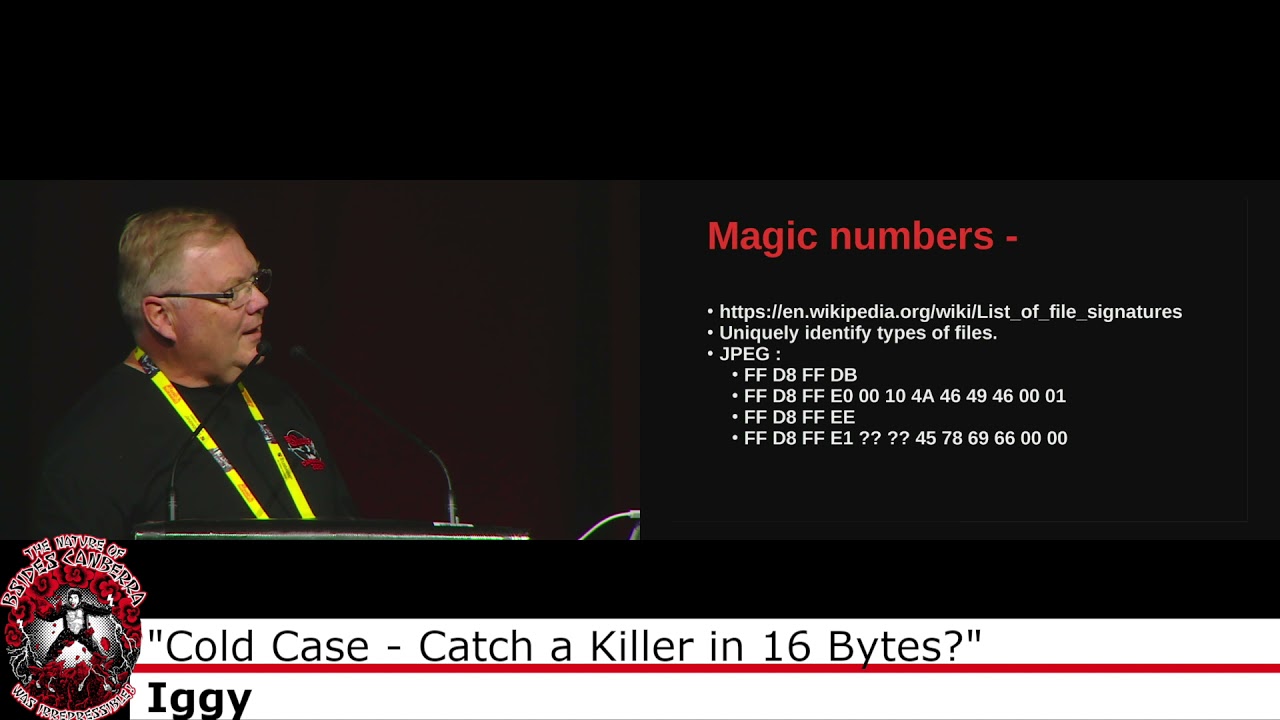 27:24
27:24 50:44
50:44 28:48
28:48 58:33
58:33 26:27
26:27